Understanding Fet Field Effect Transistor Theory and Operation In Monitor B+ Circuit Will Speed Up Your Repair Work.
Understanding the basics fet field effect transistor theory and operation in a monitor can help you to speed up the repair. I have lots of questions from my fellow repair friends and students about the fet connected in the path of B+ circuit in a monitor. That fet in the B+ circuit is actually either a "buck" or "boost" circuit.
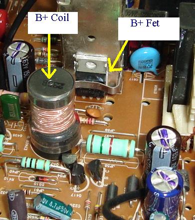
If you search around the B+ circuit, you can also find a coil, a diode, a filter capacitor and sometimes a very low ohms resistor (typical value from 0.1 ohm to 1 ohm). The coil is called as a B+ coil. Depending on how this B+ circuit is arranged, they can either "boost" a B+ voltage or "buck" a voltage down.
Almost 90 % of the monitor in the market is using the B+ boost circuit. Television normally does not have this type of circuit because they are running only on a single resolution. Older models of Monitor also do not have the Boost or Buck Circuit. The B+ voltage reaching to the pin of the flyback transformer came directly from one of the output of a power supply. If you have a Monitor schematic diagram, you could clearly see the symbol and B+ circuit components arrangement.
Some Monitor designed start with a high B+ (160-200 voltage) and buck it down depending on the mode (whether is a 640 x 480, 600 x 800 and etc). Some manufacturers preferred to design their Monitor to start with a low B+ voltage (about 45 volt) and boost it up to about 60 to 70 volts. The higher the monitor resolution the higher the B+ voltage is required to supply to the B+ pin of the flyback transformer.
The B+ circuit is located in between of the switch mode power supply and the flyback transformer and the fet field effect transistor is so easy to get damaged by a shorted horizontal output transistor or HOT. Anytime if I detected a shorted HOT I will automatically search along the B+ line to check if the B+ circuit components such as the fet field effect transistor, B+ coil, diode, filter capacitor and low ohms resistor damaged or not. Quite often if a HOT blow the B+ fet also may have the same fate.
If you come across a Monitor designed that is using Buck circuit, you may have to take precaution when checking it. Why? because whenever the mosfet developed a short circuit between the drain and the source pin, the high voltage of 160-200 volt cannot be pull down (buck) and the voltage is send directly to the B+ pin of the flyback transformer. This will cause the high voltage at the anode cap to increased to more than 30 Kilovolt and sometimes a loud 'BANG' can be heard just like when you are lighting up a fire cracker.
A Monitor B+ Circuit
This happen because the Monitor have not gone into the shutdown mode (x-ray protect). In some rare cases, the Buck circuit fet field effect transistor might blow and affected other important circuit as well. The Boost circuit is rather easy to take care, if you have any monitor that have shutdown problem, just remove the mosfet and see if it still shut down. If it working after removing the B+ fet then suspect a defective pulse signal reaching to the gate of the fet.
If it still shutdown, then check the B+ voltage and the high voltage area which include the flyback transformer, safety capacitor and feedback circuit. Typical part n umbers of fet field effect transistor used in the boost circuit are IRF634A, IRF640B, K2134, K2135 and are n channel fet. The buck circuit mosfet are IRF9620, IRF9630, IRF9640, J307, J449, J516 and many more.
They are generally the p channel type fet. Find electronic books and study the buck and boost circuits to familiarize with the components arrangement. Once you are fully understand the fet field effect transistor theory and operation or tutorial of a buck and boost circuit in a Monitor, then repairing Monitor will be a lot faster and chances to repaired it would be higher.
|
|
Copyright@ 2006-2014-www.ElectronicRepairGuide.com All Rights Reserved
