|
Audio System General Trouble Shooting
Nevertheless, audio systems are less used now-a-days due to “many-in-one” technology like DVD players, which can play back audio as well as video. But, In order to have an advanced acoustic effect, people use home theatres. It also work in similar manner to any other audio systems as previous were. The main logic behind any audio system is to amplify the audio coming from the source and also providing option to select the required frequencies like bass and treble as they require.
The audio sources are may be cassettes in case of tape recorder, the areal wire in case of radio; similarly, output of one audio system can be the input for many other audio systems. In case of home theatres the audio output taken from the DVD players or any other resources will be feed in to the input point of the audio systems. Then it will be amplified and done quality optimization in order to get good music quality. Like any other electronic circuit it also will be having power supply section and the remaining section will be related to the process of amplification and purification of the signal.
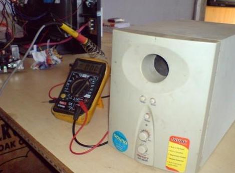
Let us take a case study for which I received a home theatre system for the service. This one is from the ‘Mercury’ company. The problem was no sound output. The system was getting switched ON. It was producing an ultimate quality of sound when it was working properly.
Picture showing the Audio Unit
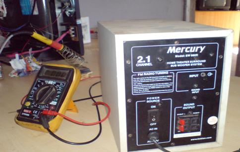
I just removed back cover of the audio system
Picture showing details of the Audio Unit
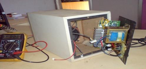
Picture showing the interior of the system
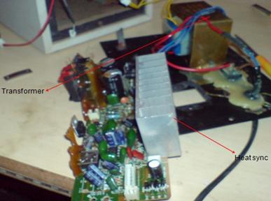
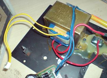
You can also observe the quality of the unit is good from the size of the transformer and also with the size of heat sink provided to the ICs of the circuit from the below picture.
Picture showing the Transformer and the HeatSink
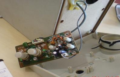
Also I removed the front cover of the system; there was also a small circuit inside which is nothing but the radio circuit (shown in below circuit).
Picture showing the Radio Circuit in the system
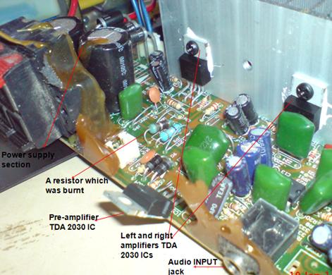
The amplifier circuit (please do not get confused with radio circuit which is another one) is designed using three ICs. One IC for the pre-amplification and other two ICs for the final amplification of left side and right side speaker out lets. For more clarification please see the below picture
Picture showing the audio circuit and components
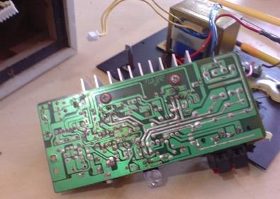
I would like to suggest any service engineer, to give careful observation to the circuit board before actually starting the repair work on it. As I observed, the board carefully, I found a resistor with burning symptoms (it is also highlighted in the above picture).When I made trace on the back, I found the resistor is the one through which power was flowing to TDA 2030 amplifier ICs.
Picture showing the Audio Circuitry
One key point I would like to share with the readers is, in any circuit, whether it is TV or other board, if any resistor bringing voltage to any IC is burnt or opened, then we should not simply replace the resistor. The main cause will be the shorted IC or any other component related to the IC. For example, if a vertical IC of TV is shorted then definitely the IC and the resistor from which the current is flowing to the IC will be getting heated. In the same way, in the above circuit the main culprit was the IC. When I switched on the set, the system was getting switched on properly. So, I did not concentrated on the power supply section. I just replaced two (both left and right) IC TDA 2030.and also for the safer side to promise the original condition, I also replaced the pre-amplifier IC TDA 2030 and also the resistor. Then I just connected two speakers and switched on the set, tuned the radio frequency to the local station, it reproduced a heaven feeling of super music. This was a case study. But, problem of different kinds will appear in different cases. The general tips I want to share with you are as follows.
1) Don’t attempt any kind of service when you are in hurry and restless.
2) Don’t work under pressure.
3) Please make sure that, you have kept all the necessary tools near by you before starting the service work.
4) If you have circuit diagram and the IC details of the circuit with you, please refer first before staring any service.
5) After opening the system, carefully at least for five minutes search thoroughly for any dry joints, loose connections, burnt components, bulged capacitors.
6) Also keep in mind that, most sensitive components in any electronic circuit are the semiconductor components like Transistors, ICs, Diodes and if used fuse and fusible resistor.
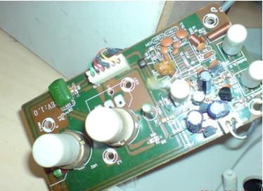
7) In any audio systems, if the audio level is fluctuating then just try by replacing the volume control, also you can put 3-4 drops of petrol in to volume control and make it correct.
Picture showing the Controls of the circuit
8)Most of the time the loose contact inside the selector switch (if used) will be the main faulty component in the circuit. Above method can be used to correct the selector switch.
9) At any cost do not ‘turn’ the IFT coils in the circuit.
10) Before removing the connectors of the circuit please note it on the book how to reconnect.
Picture showing the connector of the Transformer
11) Don’t hesitate to ask any senior about the doubts you are having.
12) Whenever a senior starts working on the circuit board, keenly observe him what he does, how he trouble shoots. Also learn the techniques which you found useful.
13) In order to get the good results always put good quality components.
14) While replacing the speakers of any audio systems please get good quality speakers.
Picture showing the speaker
15) For the problem of distorted sound, please look for the dry joints and the loose connections. Also try by cleaning the selector switch as well as volume controls.
16) For humming sound in the system, the main reason will be improper grounding of the system metallic body. Connect the metallic body of the system to the negative of the circuit board. Also, the bad filter capacitor of the power supply section will be the main reason for the humming sound.
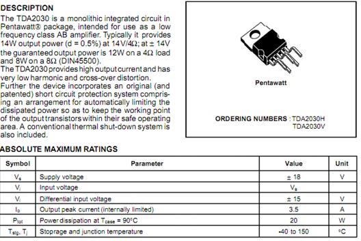
Details of the TDA 2030
Conclusion-In conclusion it is very important point to say that any audio system would be having similar stages like pre-amplifier and the amplifier. To the pre-amplifier the signal from audio source will be coupled and then it is amplified and sends to the amplifier in order to get it amplified further. Then the output from the amplifier section will be send to the speakers.
Most of the time keen observation will solve the problem very easily. Because most of the time problems are due to bad solders and loose contacts. Also, without correct knowledge don’t mishandle the system so that it gets permanently dead. Ask for suggestions from seniors and refer books for solution. Because “He who asks is a fool for five minutes, but he who does not ask remains a fool forever”.
This article was written by Raghavendra Kumar from India. He stays in Mysore a beautiful city and running two electronics service centers with his staffs and working in a software company as a software developer and as a part-time journalist for a news paper.
Please log on to his websites for more information: www.Tech-Hub.in and his old blog at http://ecare-electronics.blogspot.com/
Click here to learn how you can become a Professional in Switch Mode Power Supply Repair
Click here to learn how you can become a Professional in Testing Electronic Components
Click here to learn how you can become a Professional in LCD Monitor Repair
Click here to learn how you can find burnt resisto value
Click Here to Get 24 Best Electronics Repair Articles
Recommendation:
Recommended Mr Steve Cherubino Laptop Repair Videos For Beginners!
Recommended Mr Kent Projection Television Repair Membership website-Visit Now!
Recommended Mr Kent LCD TV Repair Membership website-Visit Now!
Recommended Mr Kent Plasma TV Repair Membership website-Visit Now! |
|
Copyright@ 2006-2014-www.ElectronicRepairGuide.com All Rights Reserved
