|
Understanding LCD Inverter Section And An Idea To Make Basic CCFL Tester (DIY)
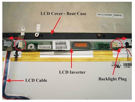
Flat-panel liquid LCDs are the display of choice in a wide range of portable products from notebook Computers, tablet PCs, and PDAs to digital cameras and portable instrumentation. Compact cold cathode fluorescent lamps (CCFLs) provide the necessary light illumination in these applications, enabling a readable display in both dim and bright ambient light.
In LCD monitor and TV, CCFLs Inverter circuit plays an important role in order to glow screen digitally. These are technically challenging circuits. First, inverters must accept a wide range of dc input voltages, typically from 3 to 14 V, and provide ac outputs of 500 to 800 V to run the CCFL tubes. Then, to burst into flames CCFL lamps, these circuits must provide momentary strike Voltages that typically are twice that of their run voltages. Many applications also require efficient Dimming capabilities to allow lamp output to match ambient (environment) light conditions and thus prolong both lamp and battery time.
There is more than one type of Inverter designs or topologies are using in liquid crystal displays (LCD) devices. Such as:
1. Buck Royer Inverter (Traditional) 2. Direct Drive (Simplified Advance)
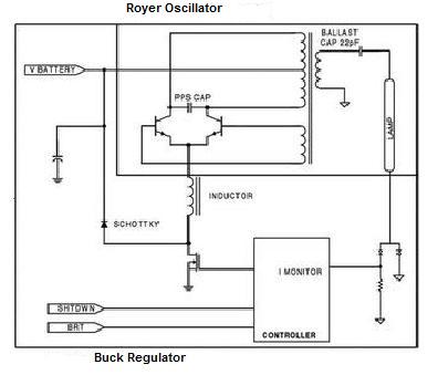
1. The traditional Buck/Royer inverter topology is essentially a combination of a step-down Buck Voltage regulator and a self-resonant Royer oscillator with an integral step-up transformer. From one decade, display makers employed a Buck/Royer inverter topology to strike and power CCFLs. This analog power topology is essentially a combination of a step-down Buck voltage regulator and a self-resonant Royer oscillator with an integral step-up transformer.
Buck Royer Inverter Traditional
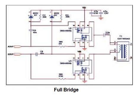
2.A simple inverter topology that could optimize performance, reduce component count, and lower costs implements a Direct Drive architecture that eliminates the inductor and resonant capacitors found in a conventional Royer oscillator.
Direct Drive Inverter
Circuit Operation Of An Inverter
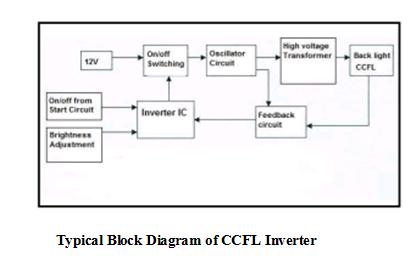
CCFLs, Inverter ideally takes DC-12 volts from power supply board in LCD Monitor / TV and In Laptop from NIMH Battery. The circuit operation and functions of LCD inverter same like Un-Interrupted Power supply (UPS) characteristics.
In addition, LCD Inverter takes DC-12 Volts from supply and starting signal pulse from main board, which fire the overall process in the inverter circuit. Switching is present, so as to start the controlled oscillation through inverter dimming controller IC chip. Which controls several functions. For example, Short circuit protection, Temperature control, Power, Humidity and Dimming in order to error free high and low CCFLs lighting. The most essential and compulsory section of an inverter is high voltage transformer. Which produces up to 600- 800 Voltages output to match ambient light conditions and requirements. It provides an alternating current source to drive the lamp. Lamp current will be the total transformer Output voltage minus the lamp voltage (lamp voltage is inversely proportional to current) divided by the capacitor's impedance.
DC – 12 VOLT REGULATED POWER SUPPLY SCHEMATIC
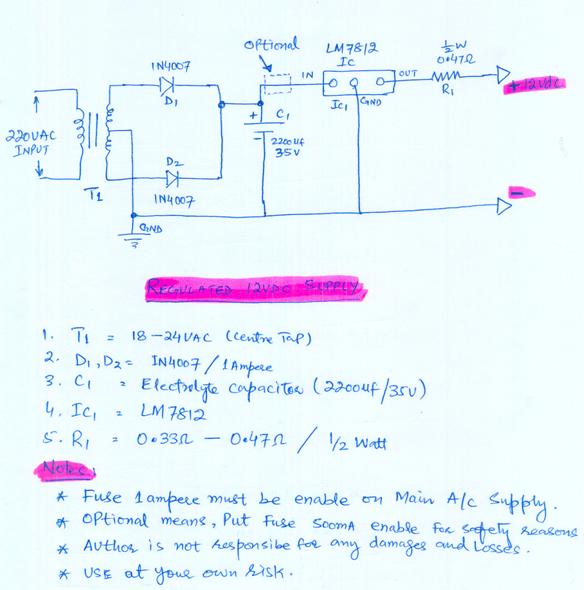
The below regulated power adapter made for CCFLs tester circuit supply and useful for other applications as per requirement. Its very simple circuit which uses center tape step down transformer T1. D1 and D2 provide full wave rectification and center tap use for grounding purpose. For filtration function uses C1, which kills the ripples of pulsating dc and to provide filter dc.
In addition to this, there is one optional point, which use for safety short circuit protection inside the circuit before regulator IC. LM 7812 – chip is using to control surges and stability of DC 12 volts. Also, to be noted that R1 is using as fuse resistance.
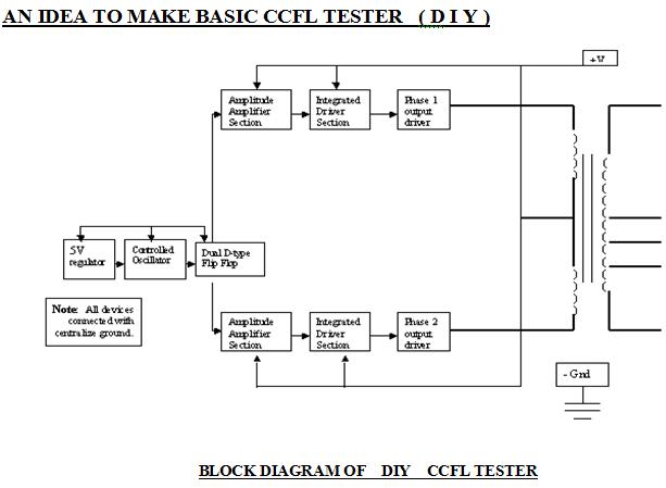
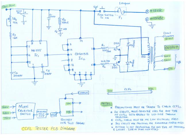
CCFLs TESTER PCB DESCRIPTION: In below circuit, IC NE555 is used to make
the multi-vibrator. The IC NE555 generates a square wave pulse train. A preset VR1 -10K is used to adjust the frequency of this pulse train. In this circuit Pin No.3 of IC- NE555 is use to output a 200 Hz square wave pulse train.
FLIP FLOP (COMPLIMENTARY IC):
IC2 –CD4013B is dual D-type flip – flop CMOS IC. Pin 11, which is input pin, is provided with 200 Hz square wave signal from the IC – NE555. The CD-4013B divides this 200Hz signal into two 50Hz bi-phase outputs. These outputs are available at the pin no. 1 and 5 of CD-4013B IC2.
OUTPUT SECTION:
Inverter output transistor Q1 – D313 and Q2 – D313 are connected to output transformer. Diode D3 and D4 function in dual mode. Iam using only one mode , In this mode they stop the transistor voltages to error free operations. When the output transformer works as LCD inverter, its last tapings i.e. 600V, 680V and 750 Volts is used to get CCFLs testing supply by multi selector switch facility. To be noted please put 400Volt / 2.2 capacitor between the high voltage probe in order to synchronization.
CONCLUSION:
To conclude all, there are several options available in technical world to check the CCFLs tubes. Here is the basic circuit solution is providing in order to gain knowledge purpose only. Any one can use above knowledge in order to make CCFLs tester at your own risk.
Notes:
Thanks you Regards Amir Mukhtar Lab Engineer and Hardware Workshop Incharge SSUET, Karachi, Pakistan. D.COM & DAE in Electronics. B-Tech (Pass) in Electronics. B-Tech (Hons) in Electronics. A+ Certified, Brainbench Certified, Linux and Computer & Electronics Specialist Certified. Etc.
The Author can be contacted at alrounder(at)hotmail.com
Click Here to check out the latest ebook by Humphrey Kimathi
Click here to learn how you can become a Professional in Switch Mode Power Supply Repair
Click here to learn how you can become a Professional in Testing Electronic Components
Click here to learn how you can become a Professional in LCD Monitor Repair
Click here to learn how you can find burnt resistor value
Click here to Get 24 Best Electronics Repair Articles
Click here to learn Basic Electronics By Greg S Carpenter
Recommendation:
Recommended Mr Steve Cherubino Laptop Repair Videos For Beginners!
Recommended Mr Kent Projection Television Repair Membership website-Visit Now!
Recommended Mr Kent LCD TV Repair Membership website-Visit Now!
Recommended Mr Kent Plasma TV Repair Membership website-Visit Now!
|
|
Copyright@ 2006-2014-www.ElectronicRepairGuide.com All Rights Reserved
