Understanding Current Sense Resistor In Electronic Circuit
Easy explanation on the functions of current sensing resistor
The current sense resistor is normally located in the switch mode power supply circuit. New monitor designed have the B+ (boost) circuit which consist of current sense resistor also. If you do switch mode power supply repair on electronic equipment, you will see the current sense resistor is connected to the source pin of the power FET (field effect transistor) and the other end to HOT GROUND, if for B+ fet the other end of the current sensing resistor is to cold ground. The value of current sense resistors is usually in the range of 0.1 ohm to about 1.2 ohm.
The current sensing resistors values are depends on the design of each power supplies. In computer monitor power supplies where pulse width modulation (pwm) ic UC3842 are used , pin 3 of this power ic is called I-sense (current sensing ic) which means current sense and this pin is connected to the source pin of power FET. The purpose of this current sense circuit is for the overcurrent protection. This circuit usually samples the voltage drop across a resistor in series with the switching fet transistor. If the current rises abnormally due to some short citcuit in the secondary side such as a shorted secondary diode or horizontal output transistor (HOT), the voltage will exceed a reference level and shutdown the pulse generator which is the PWM ic or current sense ic. This circuit provides protection to components in the event a problem occurs. In some cases where overload happen-the power section will blow and most of the time the components changed are fuse, power fet, current sensing ic (pwm ic), zener diode and current sense resistor (normally is the 0.22 and 0.33 ohms resistor).
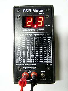
Dick Smith Esr Meter Did you know that a small change in this current sense resistor value have a big impact on the secondary output voltage? A small change in resistance value say from 0.33 ohm to 0.56 ohm can caused your output voltage to drop into half! I came across a lot of electronic repairer won't able to solve this type of problem (low output voltage) due to that they are using analog or digital meter that don't have the low ohms range for testing resistor. Without low ohms meter you can't differentiate if the low ohms resistor value have changed.
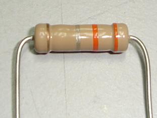
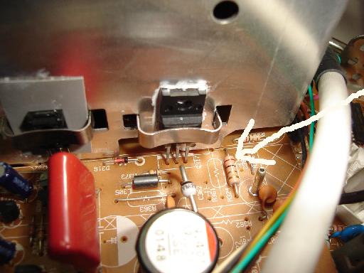
A one ohm current sense resistor nearby a B+ Fet In Monitor I myself use the Dick Smith low ohms ESR Meter which have the capabilities for testing resistor value down to 0.01 ohm! Do not worry if you don't have this low ohms meter, you can just direct replace the current sense resistor to see if the generated secondary output voltage will go back to usual or not. Another great secret is that if the current sensing resistor in the monitor B+ circuit have changed in value it will caused the output in the boost circuit to become low ( can't properly boost) and what you could see is only a small width picture. Some current sense resistor is a five band resistor. The high voltage at the anode of the crt will become low as well. Instead of 24 Kilovolt it becomes 15-18 Kilovolt. If you are not familiar which one is the current sense resistor, just look at the power fet field effect transistor and at the side of the fet you will surely see a low ohms resistor and if one of the resistor pin goes to the fet then that is the current sensing resistor. Sometimes don't mistaken a protection resistor to be a current sense resistor. A protection resistor usually connected between the positive side of the big filter capacitor to another circuit. Few more observation of the electronic board , i can guarantee that you can locate the current sensing circuits in no time.
|
|
Copyright@ 2006-2014-www.ElectronicRepairGuide.com All Rights Reserved


