How diode works and the right way to test diodes
Diodes In secondary side of Switch Mode Power Supply I will briefly explain how diode works because i'm more concern about the practical way how we deal with it when it breakdown. There are many types of diodes such as the general purpose diode, fast recovery rectifier, signal diodes, switching diodes, high frequency diodes, high voltage and stabiliser diodes, but they all share one essential characteristic: current flows in only one direction through a diode. This is probably the most important property of how diodes work. Another name for diode is rectifier and it converts an ac voltage into dc voltage. Diodes are made of different compounds, of which silicon is the main element. That's why sometime you may heard people called silicon diode. Forward biased means that the anode voltage is more positive than the cathode voltage. Reversed biased direction is the opposite of forward biased. and the anode voltage is more negative than the cathode voltage. In reverse biased, the electronc could not flow as easily as in forward bias. Obviously, it is critical that they wired into the circuit properly. Connecting a diode backwards can destroy it and may also destroy many other parts of the circuit. A technician or repair engineer must always be absolutely sure the diode is connected properly.
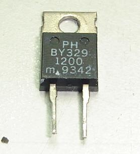
A Monitor Damper Diode Diodes are available in many types of physical forms or packages. Manufacturers may use plastic, glass, metal, or even ceramic. A silicon diode need about 0.6 volt in order for it to turn on. Germanium diode only need about 0.2 volt to turn on. Nowadays you are rarely see germanium diode in electronic circuit board. Some high voltage rectifiers may even require much higher voltage to turn on. Understanding how diode works will give you a better picture on testing diode correctly. Diodes can be check using either analog or digital multimeter but i prefered analog meter which i will expose the secrets of how to test and check a diode in the accurate way.
|
|
Copyright@ 2006-2014-www.ElectronicRepairGuide.com All Rights Reserved

