How To Use Schematic Diagram Comparison Method To Locate The Burnt Component Value One of the toughest repairs that any repairer encountered is the burnt component in electronics circuit. The usual way to find out the burnt component value is by: 1) Comparing with another similar model 2) Locate the exact schematic diagram and find out the value 3) Call your repair friend to check if he has the same equipment model in their shop or have any schematic for it or not 4) Visit electronics repair forum to ask about the value Let’s take Switch Mode Power Supplies for example. If you see one or few resistors burnt say after a power surge, there are 3 things that will come across your mind. Here are the three things: 1) You have no idea what do to when you see burnt components so you send the power supply back to your customer telling the customer there are burnt component/s and is beyond repair. 2) You will use the above 4 methods to try find the value
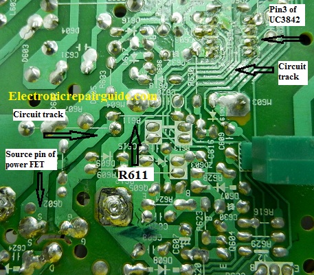
3) You tell yourself that you want to give a trial on error by replacing a random values and retest If you could find out the value then it will be great but what if you still can’t find out the value after many attempts? In this month repair newsletter I’m going to show you a method how you can locate the value of the burnt component. Although it is not 100%, at least you will have some ideas what value will the component be. The method is by comparing schematic diagrams from another quite similar equipment to roughly determine the value. For example, when you found a burnt resistor (R611) in a Monitor Switch Mode Power Supply (SMPS) for a particular model, try see at where the resistor is connected to from behind the board.
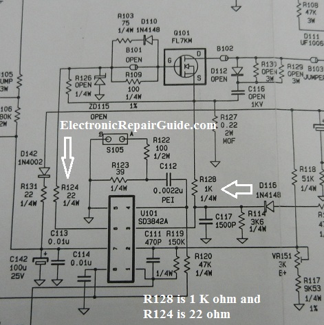
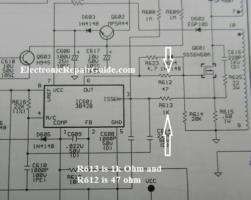
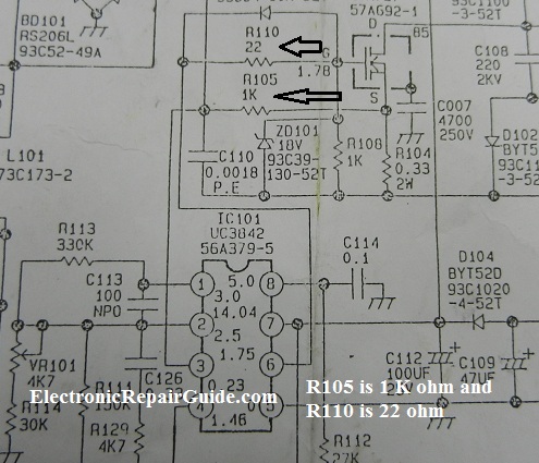
If you look at the above photo, one of the resistor pin is connected to pin 3 of UC3842 power IC and the other pin is to the source pin of power FET. Since you can’t find the exact model schematic diagram-it’s ok. What you need to do now is to find a similar Monitor model schematic. If the CRT Monitor is BENQ 19” then find another brand of 19” CRT Monitor that use the similar power IC which is the UC3842. Note: You need to download few 19” CRT Monitor schematic diagrams for comparison purpose and figure the best value for the replacement component. Please do not print a LCD TV, LCD Monitor, Plasma TV or other equipment power supply because I have found that the components value vary quite a lot. Analysis to find the right value for replacement by comparing different schematic diagrams may take a while but worth a try. Below we have 3 different CRT Monitor power supply schematic diagrams. If you compare the three schematic diagrams and concentrating on pin 3 of the power IC you will see that all the 3 models are using resistor 1 K Ohm (R128 in figure 1, R613 in figure2 and R105 in figure 3). Thus your burnt resistor value (R611) is most likely 1 K Ohm.
Figure 1
Figure 2
Figure 3
If you see the resistor value that is connected to pin 6 in figure 1- the value is 22 ohm (R124). Figure 2 have 47 ohm (R612) and figure 3 have 22 ohm (R110). In conclusion you know that the value of resistor that is connected to pin 6 generally is a low ohm value resistor. Thus, if you want to use a replacement resistor then don’t put in resistor value in the kilo ohm or mega ohm range. You should use resistor value of in between 22 to 47 ohm. If you are not sure on which value to choose then print out more schematic and find out the best value. Assuming if the power supply still did not work or produce funny symptom, I suggest that you use any lower or higher value resistor as replacement. You can use 18, 15, 12 or even 10 Ohm for the lower side. For the higher side you can use 51, 56, 68, 82, 91 or even 100 Ohm to test it out. Before you replace any component make sure you have fully check all the components in the circuit. If the power FET is shorted you may need to direct replace the power IC. Note: If you did not check for other bad components, assuming if you found the exact component value for replacement the power supply would still not be working. You thought you have used a wrong value thus you will be wasting your precious time to continue to test out some other values. The key here is you must make sure no other bad components in the circuit before you try out the schematic comparison method. I know there is lots of works involve but this is the only way you can find the value assuming you got no other information. Conclusion- I’m using a CRT Monitor as a guide to assist you. In real troubleshooting, the power IC can be of any number and burnt components can be found in any equipment. There is no guarantee in this method you can find the exact value but at least it will shed some light on what to do just in case if there are no other resources available. I hope this article will help you in locating the value of a burnt component.
Click Here To Learn How To Repair LCD Monitors With the Help Of 10 True Repair Case Histories
Click here to learn how you can become a Professional in Switch Mode Power Supply Repair Click Here To Learn DVD Player Repair By Humphrey
Click Here To Learn LCD TV Repair Tips by Kent Liew
Click Here To Learn Laptop Motherboard Repair
Click here to learn how you can become a Professional in Testing Electronic Components
Click here to learn how you can find burnt resistor value
Click here to Get 24 Best Electronics Repair Articles
Click here to learn how you can become a Professional in LCD Monitor Repair
Click here to learn how to repair Plasma Television By Damon
Recommended Basic Electronics ebook By Greg S Carpenter Recommended Mr Steve Cherubino Laptop Repair Videos For Beginners!
Recommended Mr Kent LCD TV Repair Membership website-Visit Now!
Recommended Mr Kent Plasma TV Repair Membership website-Visit Now!
Recommended Print Head Repair Guide By William Hor
Recommended Mr Kent Projection Television Repair Membership website-Visit Now!
Recommended CRT TV Repair ebook by Humphrey Kimathi
Recommended Computer Repair Course
Click Here To Learn LCD TV Repair
Click here to learn LCD TV Repair Case Histories
|
|
Copyright@ 2006-2014-www.ElectronicRepairGuide.com All Rights Reserved

