|
Understanding Transistor Functions In Electronic Circuit
If you have been in the electronic repair line you will definitely seen many transistors in the electronic circuit board. They are there for a purpose and designers use transistors to help them to do many tasks in electronic circuit. You can find transistors in the power section, color circuit, high voltage circuit and many more. Transistors come in many different type and sizes and usually labelled as “Q” in the circuit board.
What is a transistor and the function of transistor?
Transistor is a solid-state device using the element Silicon (Si) or Germanium (Ge) and it has three leads. The three leads of a transistor are Base, Collector and Emitter. Transistors and can be use to perform amplification and switching. The name transistor is derived from “trans resistor,” meaning it changes resistance. As an active device, the transistor can be used as an electronic switch. It changes between very low ohm as a short circuit for a closed switch and very high ohm as an open circuit for an open switch. In other words the transistor is either fully on with maximum current, or fully off with no current. For amplification, the transistor can amplify a signal, making it larger in amplitude. That means a small voltage placed on one of the three leads can control a large amount of current flow through the other two leads. The main difference between an NPN and a PNP transistor in a circuit is the direction in which electrons flow between emitter and collector.
I will not touch more on the theory of transistors because you can read about transistor from electronic books or even from the internet. In this article I want you to see how transistors actually work and control some of the function in electronic circuit with the help of photos and schematic diagram.
1) Transistor Act As A Switch
There are many circuits where transistors can act as a switch but here I’m only explaining few and I believe with this simple explanation you could easily understood and be able to troubleshoot the circuit that use transistors.
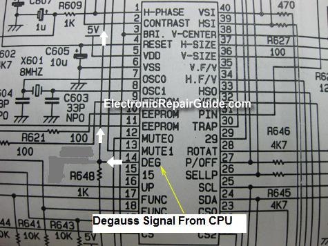
a) Degaussing circuit
Whenever you press the degauss button in the front panel of the Monitor, The Monitor CPU will send an On signal (more than 0.6 volt) to the base of Q137 and this will fully conduct the transistor (the resistance from the emitter to the collector of the transistor drops or short circuit) thus now the transistor act as a closed switch and the current will flow through the coil and the electro-magnet will pull the relay armature down and degaussing action can be executed.
b) Power saving
The white arrow is the signal sent from the CPU to Q135 in order to control the heater voltage from reaching to the CRT tube. The On signal from the CPU will trigger Q135 causing resistance to drop between the collector and emitter thus conducting Q134. Once Q134 conducts the current could flow from the emitter to the collector. This circuit is actually a power saving circuit in CRT Monitor where it shutdown the heater voltage if you did not use the Main CPU after sometimes (off signal). The moment you move the mouse or touch any key in the keyboard the CRT Monitor CPU will output an On signal to trigger Q135 again.
If you understand the above circuit then I believe you have no problem in understand the start circuit in the LCD Monitor.
The moment you power up a LCD Monitor, MCU will send an On signal to the start circuit and this signal will cause Q751 to conduct, and because of this the resistance from the emitter to the collector of the transistor drops or short circuit causing Q752 to conduct. Once Q752 conducts the current could flow from the emitter to the collector thus allowing the supply voltage 12 VDC to be present at the VCC pin of the Inverter IC.
c) B+ Circuit
A B+ circuit or boost converter (step-up converter) is a power converter with an output DC voltage greater than its input DC voltage. It is a class of switching-mode power supply (SMPS) containing at least two semiconductor switches (a diode and a transistor (FET)) and at least one energy storage element (B+ coil). Filters made of capacitors (sometimes in combination with inductors) are normally added to the output of the converter to reduce output voltage ripple.
The basic principle of the B+ circuit is:
When the power IC send a On-state signal, the B+ FET is closed, resulting in an increase in the inductor current; and when the signal is in the Off-state, the switch is open and the only path offered to inductor current is through the B+ diode D, the B+ capacitor C and the load R (flyback transformer). This result in transferring the energy accumulated during the On-state into the capacitor thus increasing the output voltage. For your information the input current is the same as the inductor current. Transistor Act As An Amplifier
You can find transistors that act as an amplifier in the CRT Monitor and Television CRT board. In older design you will see lots of transistors in the board but the newer type has fewer transistors or no transistors because all these transistors already been integrated into an IC package. Even though the transistors already built into the IC but the function is still the same which is to amplify the incoming signal from the video pre-amplifier IC.
In the above diagram the Red signal enter to the base of Q903. Amplified output is taken from the collector. The input signal is few volts peak to peak as measured on an oscilloscope. The measured output signal voltage now is about 40 to 60 Volt peak to peak (depending on model of equipment) which can be use to drive the red cathode in the CRT tube. Same explanation for the Green and the Blue circuit.
3) Transistor In Optoisolator IC
Optoisolator IC in the power supply circuit has a purpose and the purpose is to send a signal to the power IC (Feedback- FB pin) so that the power IC can control the switching time of the switch mode transformer. If the On time is long then the output voltage will be increased and if the On time is short the output voltage will be lower. This controlling function can be done thanks to the phototransistor and the LED in the Optoisolator IC.
Whenever there are changes in the secondary voltage, an error signal would be sent to the LED and because of this the light intensity in the LED will vary. The changing light intensity has influence on the phototransistor causing the resistance of the phototransistor to change too. This change of resistance will then be feedback to the power IC and the power IC will take necessary steps to adjust the switching time so that the power output will be always stable and well regulated.
Conclusion- There is actually more transistors function in electronic circuit but I would not cover it all. The reason for that was because I want you to do your own research and find your own answer. As this way would help you to understand transistor function even better. Your assignment is to get a schematic diagram and look for any transistors (FET, Bipolar, Darlington, HOT and etc) in the diagram and begin to ask yourself questions like “Why is this NPN/PNP transistor in this or that circuit?”, “Why use P-channel FET instead of N-channel FET”? and etc.
If you could find the answer I believe in the future whatever transistors found in an electronic circuit you will be able to identify the transistor function and use necessary step of troubleshooting to locate the fault fast. For your information troubleshooting a transistor that performs as a switch and amplifier is different. Okay that’s all for this month repair newsletter and hope to send to you more interesting repair article in the month to come. Take care and have a nice and a wonderful day!
Click here to learn how you can become a Professional in Testing Electronic Components
Click here to learn how you can become a Professional in LCD Monitor Repair
Recommendation:
Recommended Mr Kent Projection Television Repair Membership website-Visit Now!
Recommended Mr Kent LCD TV Repair Membership website-Visit Now!
Recommended Mr Kent Plasma TV Repair Membership website-Visit Now!
|
|


Copyright@ 2006-2014-www.ElectronicRepairGuide.com All Rights Reserved